Page updated:
March 19, 2021
Author: Curtis Mobley
View PDF
Fresnel Equations for Polarization
This page shows how polarizied light is reflected and transmitted by a level
air-water surface. The geometry is the same as for the Level 1 discussion of
Fresnel reflectance and transmittance of unpolarized light by a level sea surface.
Now, however, the state of polarization of the incident light is described by a
four-component Stokes vector, as described on the page on Stokes Vectors.
Consequently, reflection and transmission by the surface are described by
The state of polarization of a light field is specified by the four-component Stokes
vector, whose elements are related to the complex amplitudes of the electric field vector
For either air- or water-incident light,
There are four matrices to describe reflection and transmission:
The reflection and (especially) transmission of polarized light by a dielectric surface such as a level water surface are rather complicated processes, and the literature contains a number of different (and, indeed, sometimes incorrect) mathematical formulations of the equations. The formulas given in (Garcia, 2012) are used here. Note, however, that although the equations in (Garcia, 2012) are correct, some of his derivations and interpretations are incorrect, as explained by (Zhai, et al. (2012). Both papers must be used to understand the equations now presented. The equations in Garcia will be referenced by (G21) and so on; the corresponding equations in (Zhai et al. (2012) will be referenced as (Z5), etc.
The reflectance and transmittance matrices have a general formulation
for the interface between any two dielectric media a and b. Let
|
| (1) |
For water-incident light,
Let
With these preliminaries, the reflectance matrix
|
| (2) |
Here
The transmission matrix
|
| (3) |
The components of these equations are given by (G7):
Define
|
| (8) |
Then for the case of air-incident light, i.e.,
It should be noted that for the case of normal incidence,
|
| (17) |
This gives a reflectance of
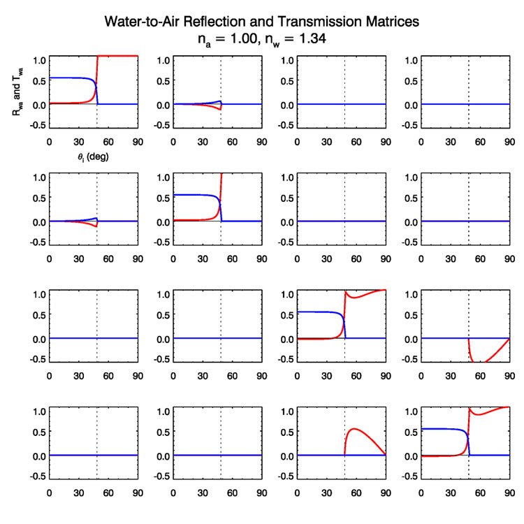
For the case of total internal reflection, i.e.,
and all elements of the transmission matrix elements are 0:
|
| (22) |
Finally, the all-important transmission factor
|
| (23) |
when computing the transmittance for diffuse Stokes vectors. These equations give everything needed to describe reflection and transmission of polarized light by a level sea surface.
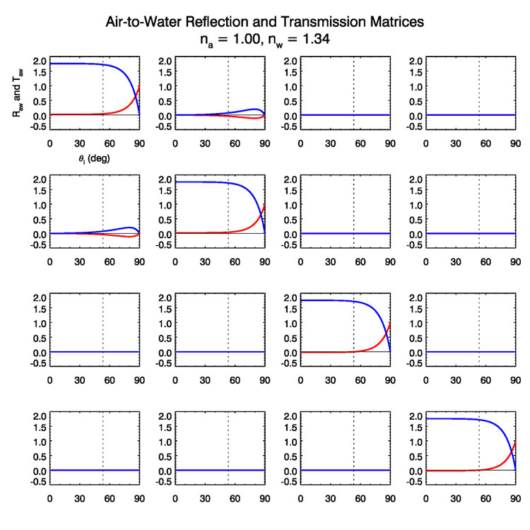
Figure 1 shows the
|
| (24) |
However, this value is indeed correct and is a consequence of the fact that we
are now dealing with a diffuse Stokes vector with units of radiance, and the

If we were dealing with coherent Stokes vectors with units of irradiance, then
the
|
| (25) |
The transmittance for normal incidence then would be
The vertical dotted line in Fig. (1) shows the location of Brewster’s angle,
|
| (26) |
which is
|
| (27) |
Thus, at Brewster’s angle, unpolarized incident radiance is totally horizontally polarized upon reflection.
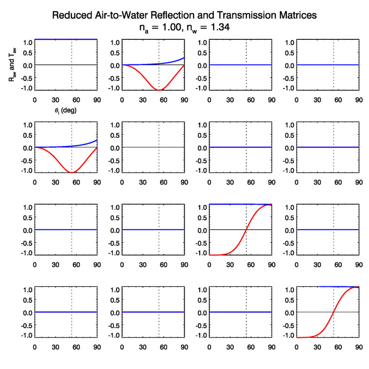
It should also be noted that the non-zero
Figure (2) shows

Figure (3) shows
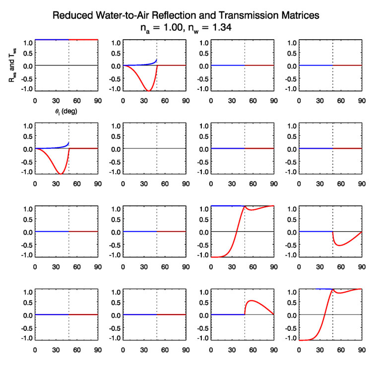
Figure (4) shows the reduced water-to-air matrices. These curves agree with
the corresponding plots in (Kattawar and Adams (1989) (their Fig. 5. The signs of
the


The non-zero matrix elements of course depend on incident angle as seen
above, but also depend weakly on the wavelength via the wavelength dependence
of

 See comments posted for this page and leave your own.